|
Assembly Precautions
Piston (1) Piston Clearance. Measure the maximum diameter of the piston, and check whether piston-to-bore clearance is normal. Pistons are available from grades 1 through 4. If the clearance is less than specified, correction by honing is needed. |
|
(2) Sharp edges inside of piston: Chamfer to 0.2 - 0.3mm (0.008 - 0.012 in).
(3) Difference in weight among cylinders: The difference must be less than 1g (0.04oz). (Piston, piston pin, piston rings and clips).  |
(4) Measure the piston ring end gap: Make corrections until the gap meets specifications.


Number of valve recesses
G2 engine ... One each for intake and exhaust valves.
G4 engine ... Two each for intake and exhaust valves.

This picture shows a G4 piston
L20B Twin cam 16valve
(5) Precautions in assembling piston pin. Before installing the pin, use an oil heater to heat the piston to 40 - 50 degrees C (104 - 122 degrees F).
(6) Check clearance at the valve recess on the top of piston. Place clay on the valve recess before installing the cylinder head, and correctly adjust the valve timing, then turn the crankshaft one complete turn. Check depresssion of the clay, to determine clearance. If abnormal resistance is felt when turning the crankshaft, it is an indication of interference between piston and valve; cease rotation of crankshaft, and correct the valve recess.
Connecting rod
(1) Grinding of connecting rod
(a) Grind the entire forged surface, except for the machined surface. The portion indicated by ----- in the figure alongside must be super finished.
|
(b) Chamfer the bolt hole portion and small end portion.
|
|
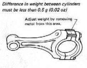
(2) Weight adjustment.
|
Difference in weight between cylinders must be less than 0.5g (0.02oz)
|
(3) Tightening of connecting rod bolt.
(a) Measure elongation of bolt to determine whether the bolt is tightened correctly. Elongation ... (0.13 - 0.14mm (0.0051 - 0.0055inch) (b) Before tightening bolt, apply Molycote to the threaded portion, and engine oil to the washer and bolt seating surface. |
|
(c) If abnormal torque is detected through the measurment of bolt elongation, change bolt and connecting rod combination, or replace the bolt with a new one.
(d) Replace the bolt with a new one every 10,000km (6,000) miles ) of operation in rally. |


Crankshaft & flywheel
(1) Lapping of pins & journals
The optional crankshaft is tufftride processed. If any sludge is found on its surface, remove by grinding with chrome oxide. Grind mainly the radius portions, taking care not to grind excessively. Modify the oil hole as shown.
|
(2) When installing a taper plug,
be sure to apply "Araldite" to the plug. |
|
Chamfer the sharp edge using an oil stone.
Finish with emery paper (#1000). |
(3) Check the out-of-roundness and taper of pins and journals.
|
(4) Measure crankshaft bend.
|
Measure the bend in #3 journal with the journals #1 and #5 supported on Vee-blocks. The bend measured on the dial gauge is half the value.
|
(5) Drive in the pilot bushing.
|
|
(6) Correction of balance.
|
|
If possible, correct the balance of the crankshaft with the clutch disc and clutch cover installed. Allowable unbalance: within 10gr-cm (0.14oz-inch/1,400 rpm
|
(7) Measuring bearing clearances.
Measuring using dial gauge, and determine oil clearance. The clearance can be changed by varying the bearing thickness.
(8) Measure the crankshaft end play and flywheel runout
Dial gauge position when measuring flywheel runout.
*Tightening torque 108 N-m (11.0kg-m, 80ft-lb).
Apply "Molycote" to the threaded portion.
Clutch
The L20B standard specification model uses the C200S type clutch. Corresponding to the enhanced engine performance, the rally model uses the C225S clutch as well as the carbon bearing cover. The clutch pressing force is available in two types [5,394N (550kg, 1,213lb) and 7,846N (800kg, 1,764lb)]. Choose the one most suitable according to engine tune-up conditions. The clutch cover utilises the existing optional part for L24.


